
In modern manufacturing, the use of threads is quite extensive. Whether it is fasteners or transmission parts, you can see threads on these parts. However, in CNC machining and engineering design, there are many cases where parts cannot be used because of the wrong thread type or tolerance level. This article will provide you with an in-depth analysis of the mainstream standards and geometric characteristics of threads, and their best practices in CNC manufacturing.
Quick Answer: Which Thread Type Should You Choose?
| Application | Recommended Thread | Why |
| Global general fastening | Metric coarse | Widely standardized |
| North American fastening | UNC | Common general-purpose inch thread |
| Fine adjustment / suitable fine-thread applications | UNF | Finer pitch |
| North American pipe connection | NPT | Tapered pipe-thread system |
| Parallel pipe connection with gasket/O-ring | BSPP / G | Parallel thread |
| ISO pressure-tight pipe thread | R / Rc / Rp | ISO 7 family |
| Power transmission | Acme / Metric Trapezoidal | Designed for screw motion |
| High axial load in one direction | Buttress | Asymmetric load-carrying profile |
What Is A Thread?

Technically, the helical structure is known as screw thread, but in daily industry habits, we usually just say thread.
In mechanical engineering, a thread is a continuous helical ridge with uniform cross-section machined or cut on the surface of a cylinder or cone. Essentially, it is a type of simple mechanical structures, a helical inclined plane wrapped around a component. This geometric mechanism can convert rotational motion into linear motion or force.
Functional Context
Due to the different uses of threads, threads are mainly divided into the following three types of functional threads:
- Fastening:It uses friction and elastic deformation to secure two parts together. Typical examples are nuts and bolts.
- Transmission:The role of threads in transmission components is to transfer power or precisely control displacement, such as the ball screws you are familiar with.
- Sealing: Thread types such as NPT pipe threads can help seal partsto prevent fluid leakage
Core Elements Of Screw Thread

In CNC machining, to accurately describe or machine a thread, you must understand its various elements. Below, I will introduce them one by one so that you can have a clearer understanding.
Diameter
Threads have three different diameter concepts, which determine the size of the thread.
Major Diameter(d / D)
The nominal diameter of the thread. It is the diameter of the imaginary cylindrical surface tangent to the crest of the external thread or the bottom of the internal thread.
Minor Diameter(d1 / D1)
The minor diameter is the diameter of the imaginary cylindrical surface tangential to the external thread root or internal thread crest. It determines the minimum cross-sectional size of the thread strength.
Pitch Diameter(d2 / D2)
The most critical inspection dimension. It is an imaginary cylinder between the major diameter and the minor diameter, and its tooth width is equal to the groove width.
Pitch & Lead
The two most easily confused concepts. Let me clarify them for you here.
Pitch(P)
Pitch refers to the axial distance between two corresponding points on the median diameter line of adjacent threads, which determines the density of the threads.
Lead(L)
Lead is another concept. It refers to the axial displacement of a thread over one complete rotation.
Formula: L=n×P (n is the number of thread starts)
Thread Angle(α)
The thread angle refers to the angle between the sides of two adjacent threads in the axial section of the thread. It determines the type of thread and its self-locking performance.
- 60°: ISO metric thread, US inch thread.
- 55°: British Whitworth thread.
- 30°/ 29°: Trapezoidal thread, used for transmission.
Crest & Root
Crest
Refers to the highest point of the thread tooth profile.
Root
Refers to the lowest part of the threaded tooth groove, opposite to the crest.
Hand of Thread
You also know that threads have a hand of thread, and they are divided into two categories according to different directions.
Right-hand
Right-handed bolts will screw into the nut when rotated clockwise. This is also the default standard in the industry unless there are special requirements.
Left-hand
Correspondingly, a left-hand bolt will screw in the nut when it is rotated counterclockwise. Generally, this kind of left-handed component is only used in special scenarios.
Different Types of Thread

There are actually many ways to classify thread types. Due to its history and regional preferences, combined with the unique load-bearing capacity of threads themselves, multiple standards now exist. However, each type of thread also has its uses. In the past, few sites would specifically categorize these types for you. But today, our DSR company will classify the types of threads in detail according to a certain indicator, so that you can understand the content of thread types clearly and easily.
Classification By Thread Position Type
Threads are divided into two types according to their position: internal threads and external threads. You should know that this distinction can directly determine the machining strategy, tool selection and tolerance standard setting in CNC machining.
External Threads

Also known as a male thread. External threads are threads formed on the external surface of a cylinder or cone. Common components of this thread include bolts, screws, studs, lead screws, etc.
CNC machining strategy:
- Single Point Turning: Your various non-standard threaded parts are easily processed with thread inserts, providing high flexibility.
- Thread Rolling: This process is well-suited for mass production. Unlike cutting, it primarily forms threads by extruding the material, so rolled threads can improve fatigue strength and surface integrity compared with cut threads.
- Thread Milling: This process is mainly used for machining large-diameter external threads or large workpieces that are difficult to rotate.
Regarding dimensions, what you need to pay attention to is that the Major Diameter is the primary inspection criterion. If the measured value is too small, the thread fit will become loose. If the measured value is too large, the components cannot be assembled.
Internal Threads

Also known as a female thread, an internal thread is the thread formed on the inner surface of a hole.Common components of this type include nuts, hydraulic interfaces, etc.
CNC machining strategy:
- Tapping: The most common method. First, drill a bottom hole in the workpiece with a drill bit, and then use a tap for machining。
- Thread Milling: If you need high-value internally threaded parts, this is your first choice. This is because thread milling generally does not damage the workpiece.
Additionally, I must remind you that the minor diameter of the workpiece is extremely important.
Classified By Thread Profile
There are many types of thread profiles. We can divide them into the following types according to the thread profile dimension and profile shape. You need to know that different geometric shapes determine the mechanical properties of the threads, thereby deciding whether they are used for fastening or transmission.
Triangular Thread

As the name suggests, the thread profile is triangular with a wider base. This is also the most common and widely used thread profile. Its typical application includes fastening parts such as nuts and bolts. Milling machining, lathe machining, and other processes can produce this type of thread.
You also know that the triangular structure has the best stability, and the triangular cross-section can also generate huge friction and has good self-locking performance.
Trapezoidal Thread

The thread profile is isosceles trapezoidal, that is, the top is thin and the bottom is flat. It is mainly used for two-way transmission. The main advantage of trapezoidal threads is that rectangular threads have high strength and thicker roots. Its main applications include lead screws, linear actuators, etc.
This type of threaded assembly has relatively good machinability, and even if wear occurs, the gap can be eliminated by tightening.
Square Thread

The thread profile is square and has an extremely strong root. This thread is mainly used for force transmission. Its radial component of force is zero, resulting in the highest transmission efficiency. Additionally, this thread is primarily suitable for screw jacks, presses, heavy lifting equipment, and similar devices.
Furthermore, from a CNC machining perspective, this threaded component is extremely difficult to process. During the entire machining process, chip evacuation is challenging, tool wear is rapid. And once the thread profile is worn, the gap will be difficult to adjust.
Buttress Thread

The thread profile is asymmetrical. The working surface on one side is nearly vertical, and the non-working surface on the other side is inclined. It can only withstand force in one direction. Typical applications include hydraulic press columns, jacks, etc.
Knuckle Thread

The geometric feature of this thread is that the thread profile is connected by arcs without sharp edges, and its top and bottom are semicircular. Knuckle threads have high fatigue strength and static strength, and are not prone to dust and sediment accumulation. It is easy to clean and resistant to wear and tear. Therefore, components of this thread type are widely used in harsh environments. Knuckle thread applications mainly include light bulb interfaces, mining machinery, train carriage couplings, etc.
Thread Profile Comparison Table
| Profile Name | Thread Angle | Friction & Self-Locking | Transmission Efficiency | Primary Application |
| Triangular | 60° / 55° | High | Low | Fastening |
| Trapezoidal | 29° / 30° | Moderate | High | Power Transmission |
| Square | 0° | Low | Highest | Heavy Load Lifting |
| Buttress | 3°/30° | Low | High | Uni-directional Loads |
| Knuckle | Continuous Arc | Moderate | Moderate | Debris Resistance |
Classified By The Number of Thread Helix Lines
Single-Start Thread

This is your most common thread type. Single-start threads have only one helical line wound on a cylinder, and its pitch is the same as its lead. Simply put, when the screw rotates one full turn, the nut advances axially by one pitch length. The single-head thread has strong self-locking, its lift is small, and the friction is large. Most conventional fasteners are of this single-head thread type.
Double-Start Thread

The structure of this thread is on the surface of a cylinder, with two separate helical lines wound in parallel. The starting points of these two helical lines are symmetrically distributed at 180° on the cylinder. At this time, the double-start thread lead = 2 times the double-start thread pitch.
The moving speed of double-start threads is also twice that of ordinary single-start threads. Many mineral water bottle caps, medicine bottle caps, and fire hydrant interfaces used in our lives are of this double-start thread type.
Multi-Start Thread

And when you need faster movement speed and higher transmission efficiency, you need to use multi-start threads. This thread structure has two or more parallel helixes evenly distributed on a cylinder. You must have concluded the formula relationship through the above two thread types.
Multi-start thread formula: Lead = Pitch × Number of starts (L=P×n).
This type of thread is labor-saving and moves quickly. And multi-start thread applications include the lead screw of 3D printers, valve stems, etc.
* Multi Start Thread Calculator:
DSR Multi Start Thread Calculator
Classified By Thread Inclination
Threads are mainly divided into tapered threads and cylindrical threads according to their inclination. This classification method determines the sealing method and force principle of the thread.
Tapered Thread

Tapered thread is shaped like a cone, it is a thread that gradually tapers along its contour. Some common tapered pipe-thread systems, such as NPT and ISO 7-1 pipe threads, use a nominal taper of 1:16. The working principle of this thread is wedging action. The main applications of tapered threads include connecting water pipes, fuel pipes, lubricant pipes, etc.
Cylindrical Thread

It can also be called straight thread. The shape of a cylindrical thread is a cylinder. Its large, medium, and small diameters remain unchanged. Its working principle mainly relies on the frictional force on the thread flanks for locking.
You should note that this thread does not have sealing capabilities, but requires the assistance of third-party components, such as O-ring, bonded washer and flat gaskets.
Classified By Thread Rotation Direction
The definition concept has been discussed above, so I won’t go into too much detail here. Here I mainly introduce to you the operation and identification methods, which are also the points that many people have doubts and are interested in.
Right-Hand Thread

Default standard. When you rotate the component clockwise, it’s tightening, and when you rotate it counterclockwise, it’s loosening.
Identification method:
- Side View:Place the screw vertically and observe the visible side of the helix. If the spira is lower on the left and higher on the right, it is right-handed.
- Gesture Method:Extend your right hand, with the thumb pointing in the axial movement direction and the curved direction of the four fingers indicating the rotation direction.
Left-Hand Thread

Threads for special purposes. Left-hand threads are the exact opposite of right-hand threads. When you rotate the component counterclockwise, it tightens, and when you rotate it clockwise, it simply loosens.
Identification method:
- Side View: You place the components vertically, and the spiral is low on the right and high on the left, which is the left-hand thread.
- Marking: Many left-hand nuts will have an annular groove cut into the hexagonal surface as a warning.
Classified By Thread Pitch
In addition, we can also divide threads into the following three types based on the pitch of the thread, that is, the distance between the vertices.
Coarse Pitch Thread

Standard configuration. Coarse threads have a larger pitch and a deeper thread profile. It is durable and quick to assemble and disassemble, suitable for most applications. Even minor damage will not affect its performance.
Fine Pitch Thread

Fine-pitch threads have smaller pitches and shallower thread profiles. Due to its smaller helix angle, it has strong vibration resistance and tensile strength. Fine threads are also the perfect choice for applications with specific strength requirements. As for the disadvantages, these threads are prone to cross-threading and are not dirt-resistant.
Extra Fine Pitch Thread
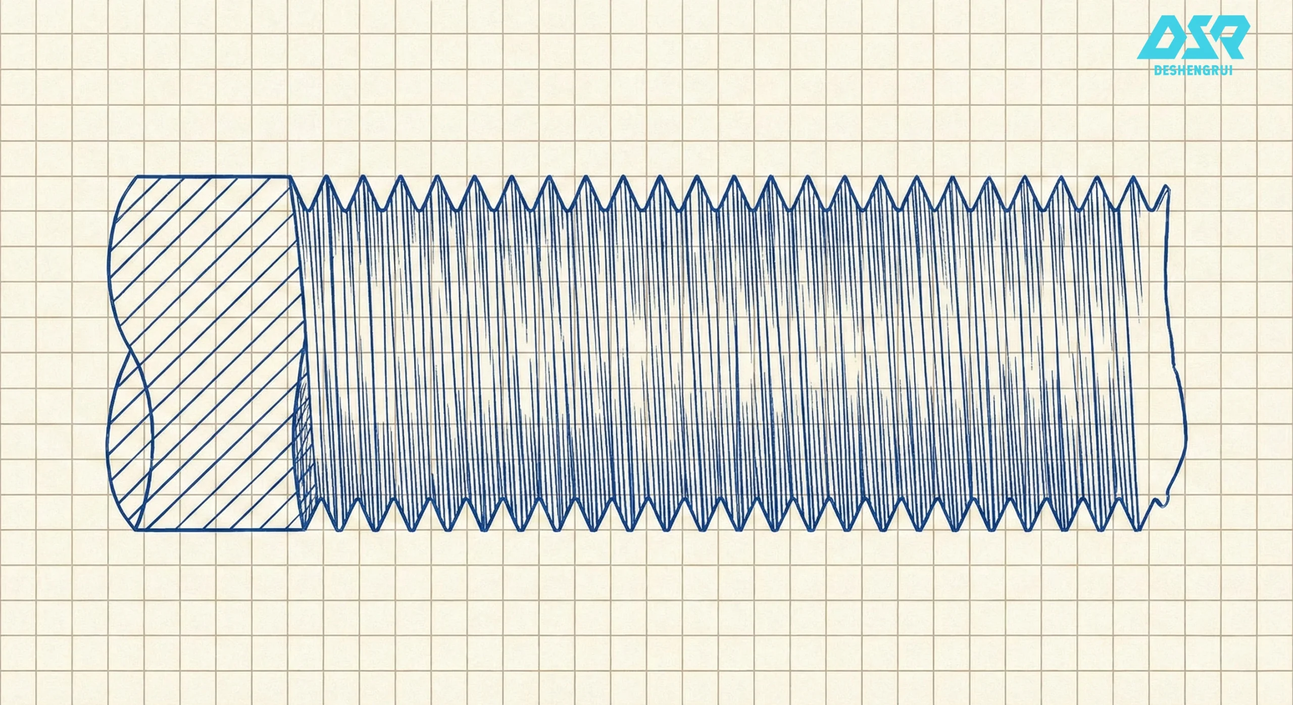
This type of thread has an extremely fine pitch. Extra fine pitch thread is also used in extremely limited spaces, typical components such as ultra-thin wall fittings.
CNC Thread Design Guidelines

After introducing so many types of thread structures, let’s talk about thread design. It can be said that whether a thread can be machined on a CNC is also a very critical issue. Many times, problems with a part’s threads are not due to insufficient machine capability, but rather because they were not well-designed at the design stage.
Leave Enough Space at the Bottom of Blind Threaded Holes
You probably also know that when tapping blind holes, the front end of the tap usually has a chamfer or cutting portion, so a full-form thread cannot be formed near the bottom of the hole. Even though thread milling is more flexible in this regard, it also requires tool clearance,clearance for tool entry and exit, and bottom clearance.
Therefore, do not require the full usable thread to extend all the way to the bottom of blind holes. You need to leave space for the drill point, the tap’s cutting taper, or tool runout for thread milling. And it’s best if your drawings also distinguish between hole depth and full thread depth.
Add a Chamfer at the Thread Entrance
You can add an appropriate chamfer at the thread entrance. This can improve bolt entry, reduce damage to the first thread, and minimize burrs. At the same time, the chamfer is also very beneficial for tool entry during tapping or thread milling.
Our common design practices typically use small angle chamfers or approximately 45° chamfers. Of course, the actual dimensions should still be determined based on your own thread diameter and functionality.
Avoid Unnecessarily Long Thread Engagement
Excessively long threads does not necessarily proportionally increase connection strength, but it will increase machining time, make chip evacuation more difficult, and increase the risk of tool wear or breakage.
In fact, the effective thread length should be determined based on the materials, loads, and joint design of your actual project. Don’t simply assume that the deeper the thread, the better.
Be Careful with Small Threads in Difficult Materials
When designing threaded features, you should also consider the machinability of the material. Small-diameter, deep threads are more difficult to produce in materials such as stainless steel, titanium alloys, and high-temperature alloys, where tool wear, chip evacuation problems, and tap breakage can become more likely.
Therefore, for these types of parts, you can consider thread milling or other more suitable processes based on size and batch.
Consider Wall Thickness Around Threaded Features
This is a point that many designers tend to overlook. If threaded holes are too close to the edge of a part or located on thin-walled bosses, local deformation is very likely to occur during machining.
Therefore, when designing, you should reserve sufficient material around the threads to ensure complete thread form and ensure reliable assembly.
Account for Surface Treatment
Anodizing, plating, coating or other surface treatments may alter the final dimensions of threads. Therefore, for threads with tight tolerances, you need to consider film thickness, masking and machining compensation in advance. This is also to avoid situations where parts become too tight for assembly or fail gauge inspection after surface treatment.
Prefer Standard Thread Sizes Where Possible
If there are no special functional requirements, I recommend that you prioritize the use of standard Metric, UNC, UNF, NPT, or BSP threads. The reason is simple. Standard threads are usually easier to find tools, gauges, and matching fasteners for, and are also more conducive to controlling your costs and delivery times.
Choose the Threading Process Based on the Part
Tapping is not the only option for producing internal threads. For larger diameter threads, small batch production, or high-value parts, thread milling can sometimes provide better dimensional control. At the same time, even if tool damage occurs, there are fewer difficult situations like tap breakage getting stuck in the hole.
As for specific process selection, it should still be determined based on your project’s material, diameter, depth, tolerance and quantity.
Current Thread Standards in 2026

It should be noted that thread standards are revised periodically, so you should confirm the current standards referenced in the drawings before manufacturing or inspection.
| Thread System | Current Reference |
| ISO Metric Threads | ISO 68-1, ISO 261, ISO 965 series |
| Unified Threads (UNC/UNF) | ASME B1.1 |
| NPT / NPS | ASME B1.20.1 |
| BSPT / R / Rc / Rp | ISO 7-1 |
| BSPP / G | ISO 228-1 |
| Metric Trapezoidal Threads | ISO 2901 / related ISO 290x series |
Thread International Standard Analysis

The world’s thread standards are primarily divided into three major systems: metric threads, Unified threads, and British Standard Pipe threads. This is also one of the areas where mechanical machining professionals are most prone to confusion. Next, I will introduce them in detail so that you can quickly become familiar with them.
Metric Thread
Metric thread is arguably the world’s most popular and widely used ISO metric thread standard. Many countries in the world are using this standard, such as China, Europe, and Japan. M is the code letter for metric threads. Metric threads are threads defined by the distance between each vertex, measured in millimeters (mm). In addition, the standard specifies design rules, dimensions and tolerances.
Metric Thread Tolerance System
Actually, the tolerance code of metric threads consists of a number + a letter (e.g., 6H, 6g). This code will tell you whether the screw and nut are loose or tight when screwed together.
Code structure:
Code = Tolerance Class (number) + Fundamental Deviation (letter)
1. Number (tolerance class):Indicates the precision grade.
The smaller the number, the higher the precision, and the more difficult the machining.
- Class4, 5: Precision grade.
- Class6: Medium grade (industrial standard, most commonly used).
- Class7, 8: Rough grade.
2. Letter (Fundamental Deviation): Indicates the degree of tightness.
The position of the thread size relative to the zero line.
- Uppercase letter = Internal thread
- Lowercase letter = External thread
Common Thread Tolerance Codes
| Code | Type | Meaning |
| H | Internal Thread (Nut) | Zero Deviation. The standard tolerance for nuts. No clearance at the basic size. |
| G | Internal Thread (Nut) | Positive Deviation. Provides a small clearance. |
| h | External Thread (Bolt) | Zero Deviation. The upper limit is the basic size. |
| g | External Thread (Bolt) | Negative Deviation. Provides a small clearance. |
| e | External Thread (Bolt) | Large Negative Deviation. Provides a large clearance. |
Metric Thread Chart
The complete metric thread chart is provided for you below.
| Size | Standard Coarse Pitch | Common Fine Pitch | Tap Drill (Ø) |
| M1.6 | 0.35 mm | — | 1.25 mm |
| M2 | 0.4 mm | — | 1.6 mm |
| M2.5 | 0.45 mm | — | 2.05 mm |
| M3 | 0.5 mm | — | 2.5 mm |
| M4 | 0.7 mm | — | 3.3 mm |
| M5 | 0.8 mm | — | 4.2 mm |
| M6 | 1.0 mm | — | 5.0 mm |
| M8 | 1.25 mm | 1.0 mm | 6.8 mm |
| M10 | 1.5 mm | 1.25 / 1.0 mm | 8.5 mm |
| M12 | 1.75 mm | 1.5 / 1.25 mm | 10.2 mm |
| M14 | 2.0 mm | 1.5 mm | 12.0 mm |
| M16 | 2.0 mm | 1.5 mm | 14.0 mm |
| M18 | 2.5 mm | 1.5 mm | 15.5 mm |
| M20 | 2.5 mm | 2.0 / 1.5 mm | 17.5 mm |
| M22 | 2.5 mm | 2.0 / 1.5 mm | 19.5 mm |
| M24 | 3.0 mm | 2.0 mm | 21.0 mm |
| M27 | 3.0 mm | 2.0 mm | 24.0 mm |
| M30 | 3.5 mm | 2.0 mm | 26.5 mm |
| M33 | 3.5 mm | 2.0 mm | 29.5 mm |
| M36 | 4.0 mm | 3.0 mm | 32.0 mm |
Practical Tips for Engineers:
- Coarse is the Default: In the metric system, if a drawing only specifies M5 without specifying the pitch, it defaults to M5 x 0.8 (coarse thread).
- Tap Drill Calculation Rule: You can use this empirical formula to calculate the drill diameter before tapping.
Ddrill=Dnominal−Ppitch
- When to Use Fine Threads: Fine pitch is usually used in scenarios requiring higher strength, more precise adjustment, or thin-walled fittings.
Unified Thread Standard
UTS is mainly used in the United States and Canada, and it is also used in the aerospace and oil industries around the world. Standard threads are typically V-shaped threads with a 60-degree angle and are measured in inches. The standard defines pitch as TPI, which refers to the number of threads per inch.
Example interpretation: 1/2-13 UNC
- “1/2”: nominal diameter (inches).
- “13”: 13 threads per inch (TPI).
- “UNC”: Unified National Coarse thread series.
Tolerances Classes for Unified Thread Standard (UTS)
The US tolerance class system is completely different from the metric system, it uses a “number + letter” combination.
Code Structure:
Class Code = Fit Class (number) + Thread Type (letter)
1. Letters: Thread Type
- A = External Thread.
- B = Internal Thread
2. Numbers: Fit Class
Numbers are divided into 1, 2, and 3 classes. The larger the number, the tighter the fit and the higher the accuracy.
The Three Classes
1. Class 1——1A / 1B
This is the roughest class with large allowance. It is used for fasteners in harsh environments
2. Class 2——2A / 2B)
Common general-purpose class . It is used in the general machinery industry, automotive parts industry, etc.
- 2A: Leaves a slight allowance.
- 2B: Standard tolerance.
3. Class 3——3A / 3B
This is a high precision class with almost no allowance. It is used in aerospace, precision instruments, and other industries. Class 3 has tighter tolerance, and the cost is also high. Bolts and nuts fit very tightly.
Unified Thread Standard
Below is the complete specification table for the Unified Thread Standard (UTS). I have divided it into numbered sizes and fractional sizes.
Numbered Sizes(Small Diameters)
This table applies to small fasteners with a diameter of less than 1/4 inch.
| Nominal Size | Major Diameter | UNC (Coarse) TPI | UNC Tap Drill | UNF (Fine) TPI | UNF Tap Drill |
| #0 | 0.060″ (1.52mm) | — | — | 80 | 3/64″ |
| #1 | 0.073″ (1.85mm) | 64 | #53 | 72 | #53 |
| #2 | 0.086″ (2.18mm) | 56 | #50 | 64 | #50 |
| #3 | 0.099″ (2.51mm) | 48 | #47 | 56 | #45 |
| #4 | 0.112″ (2.84mm) | 40 | #43 | 48 | #42 |
| #5 | 0.125″ (3.18mm) | 40 | #38 | 44 | #37 |
| #6 | 0.138″ (3.51mm) | 32 | #36 | 40 | #33 |
| #8 | 0.164″ (4.17mm) | 32 | #29 | 36 | #29 |
| #10 | 0.190″ (4.83mm) | 24 | #25 | 32 | #21 |
| #12 | 0.216″ (5.49mm) | 24 | #16 | 28 | #14 |
Fractional Sizes (Standard)
This table is for common mechanical fasteners with a diameter of 1/4 inch and above.
| Nominal Size | Major Diameter | UNC (Coarse) TPI | UNC Tap Drill | UNF (Fine) TPI | UNF Tap Drill |
| 1/4″ | 0.250″ (6.35mm) | 20 | #7 (or 13/64″) | 28 | #3 (or 7/32″) |
| 5/16″ | 0.3125″ (7.94mm) | 18 | F (or 17/64″) | 24 | I (or 17/64″) |
| 3/8″ | 0.375″ (9.53mm) | 16 | 5/16″ | 24 | Q (or 21/64″) |
| 7/16″ | 0.4375″ (11.11mm) | 14 | U (or 23/64″) | 20 | 25/64″ |
| 1/2″ | 0.500″ (12.70mm) | 13 | 27/64″ | 20 | 29/64″ |
| 9/16″ | 0.5625″ (14.29mm) | 12 | 31/64″ | 18 | 33/64″ |
| 5/8″ | 0.625″ (15.88mm) | 11 | 17/32″ | 18 | 37/64″ |
| 3/4″ | 0.750″ (19.05mm) | 10 | 21/32″ | 16 | 11/16″ |
| 7/8″ | 0.875″ (22.23mm) | 9 | 49/64″ | 14 | 13/16″ |
| 1″ | 1.000″ (25.40mm) | 8 | 7/8″ | 12 | 59/64″ |
Pipe Threads
Pipe threads are used for pipe connections and usually require tightness of the pipes.
BSP(British Standard Pipe)
Common water pipe and air pipe standards in Europe, Asia and Australia. Derived from Whitworth thread. The thread angle is 55°.
- BSPP (G-thread): Parallel pipe thread, relying on O-rings or gaskets sealing.
- BSPT (R = tapered external thread/ Rc = tapered internal thread/ Rp = parallel internal thread): Tapered pipe thread, taper 1:16. It seals through thread interference fit and is also the mainstream choice in Europe and Asia.
BSP Thread Chart
| Nominal Size (G/R) | Threads Per Inch (TPI) | Major Diameter (OD) | Tap Drill (BSPT/Taper) | Tap Drill (BSPP/Parallel) |
| 1/8″ | 28 | 9.73 mm | 8.2 mm | 8.8 mm |
| 1/4″ | 19 | 13.16 mm | 11.0 mm | 11.8 mm |
| 3/8″ | 19 | 16.66 mm | 14.5 mm | 15.25 mm |
| 1/2″ | 14 | 20.96 mm | 18.0 mm | 19.0 mm |
| 3/4″ | 14 | 26.44 mm | 23.5 mm | 24.5 mm |
| 1″ | 11 | 33.25 mm | 29.5 mm | 30.75 mm |
| 1-1/4″ | 11 | 41.91 mm | 38.0 mm | 39.5 mm |
| 1-1/2″ | 11 | 47.80 mm | 44.0 mm | 45.0 mm |
| 2″ | 11 | 59.61 mm | 55.5 mm | 57.0 mm |
NPT(National Pipe Taper)
Common piping standards in North America. It is also a taper pipe thread with an angle of 60°, and its crest and root are flat. Additionally, it is used in the hydraulic industry to connect hoses and fittings.
NOTE:
You should never use NPT and BSPT interchangeably. Although both are tapered pipe threads and look exactly the same, they are absolutely not interchangeable. There are three reasons:
1. NPT is 60° and BSPT is 55°.
2. Their threads per inch (TPI) are different for most sizes. You can also visually see the difference through the table below.
| Dimensions (inches) | NPT (US) TPI | BSPT (Imperial) TPI |
| 1/8″ | 27 | 28 |
| 1/4″ | 18 | 19 |
| 3/8″ | 18 | 19 |
| 1/2″ | 14 | 14 |
| 3/4″ | 14 | 14 |
| 1″ | 11.5 | 11 |
3. The thread crest shapes differ. NPT thread crests and roots are flat, andBSPT thread crests and roots are rounded.
NPT Thread Chart
| Nominal Pipe Size (NPS) | Threads Per Inch (TPI) | Approx. Outside Dia. (OD) | Tap Drill Size |
| 1/8″ NPT | 27 | 0.405″ (10.29mm) | R (or 11/32″) |
| 1/4″ NPT | 18 | 0.540″ (13.72mm) | 7/16″ |
| 3/8″ NPT | 18 | 0.675″ (17.15mm) | 37/64″ |
| 1/2″ NPT | 14 | 0.840″ (21.34mm) | 23/32″ |
| 3/4″ NPT | 14 | 1.050″ (26.67mm) | 59/64″ |
| 1″ NPT | 11.5 | 1.315″ (33.40mm) | 1-5/32″ |
| 1-1/4″ NPT | 11.5 | 1.660″ (42.16mm) | 1-1/2″ |
| 1-1/2″ NPT | 11.5 | 1.900″ (48.26mm) | 1-47/64″ |
| 2″ NPT | 11.5 | 2.375″ (60.33mm) | 2-7/32″ |
| 2-1/2″ NPT | 8 | 2.875″ (73.03mm) | 2-5/8″ |
| 3″ NPT | 8 | 3.500″ (88.90mm) | 3-1/4″ |
British Standard Thread
BSW (British Standard Whitworth)
Whitworth thread is named after the British engineer Joseph Whitworth. Its code is W. It has a thread angle of 55° with rounded crests and roots.
BSF (British Standard Fine)
British Standard Fine Thread. This thread has a 55° angle but more threads per inch.
Other Thread Chart
Here I have supplemented various thread specification tables that you might use. I hope they can be helpful to your work.
UN Thread Chart
| Nominal Diameter | Major Diameter (Decimal) | 8-UN (8 TPI) | 12-UN (12 TPI) | 16-UN (16 TPI) |
| 1-1/8″ | 1.1250″ | Standard | Standard | — |
| 1-1/4″ | 1.2500″ | Standard | Standard | — |
| 1-3/8″ | 1.3750″ | Standard | Standard | — |
| 1-1/2″ | 1.5000″ | Standard | Standard | — |
| 1-5/8″ | 1.6250″ | Standard | Standard | — |
| 1-3/4″ | 1.7500″ | Standard | Standard | — |
| 1-7/8″ | 1.8750″ | Standard | Standard | — |
| 2″ | 2.0000″ | Standard | Standard | — |
| 2-1/4″ | 2.2500″ | Standard | Standard | — |
| 2-1/2″ | 2.5000″ | Standard | Standard | — |
| 2-3/4″ | 2.7500″ | Standard | — | — |
| 3″ | 3.0000″ | Standard | — | — |
PG Thread Chart
An old German standard used for cable glands and electrical conduits.
| PG Size | Major Diameter (mm) | Major Diameter (Inch) | TPI (Threads Per Inch) | Tap Drill Size (mm) |
| PG 7 | 12.5 mm | 0.492″ | 20 | 11.4 mm |
| PG 9 | 15.2 mm | 0.598″ | 18 | 14.0 mm |
| PG 11 | 18.6 mm | 0.732″ | 18 | 17.25 mm |
| PG 13.5 | 20.4 mm | 0.803″ | 18 | 19.0 mm |
| PG 16 | 22.5 mm | 0.886″ | 18 | 21.25 mm |
| PG 21 | 28.3 mm | 1.114″ | 16 | 26.8 mm |
| PG 29 | 37.0 mm | 1.457″ | 16 | 35.5 mm |
| PG 36 | 47.0 mm | 1.850″ | 16 | 45.5 mm |
| PG 42 | 54.0 mm | 2.126″ | 16 | 52.5 mm |
| PG 48 | 59.3 mm | 2.335″ | 16 | 57.8 mm |
NPS Thread Chart
NPS refers to a family of parallel pipe threads.
| Nominal Pipe Size | TPI (Threads Per Inch) | Major Diameter (OD) | Tap Drill Size (Straight) |
| 1/8″ NPS | 27 | 0.405″ (10.3mm) | 11/32″ (8.7mm) |
| 1/4″ NPS | 18 | 0.540″ (13.7mm) | 7/16″ (11.1mm) |
| 3/8″ NPS | 18 | 0.675″ (17.1mm) | 37/64″ (14.7mm) |
| 1/2″ NPS | 14 | 0.840″ (21.3mm) | 47/64″ (18.3mm) |
| 3/4″ NPS | 14 | 1.050″ (26.7mm) | 59/64″ (23.4mm) |
| 1″ NPS | 11.5 | 1.315″ (33.4mm) | 1-5/32″ (29.4mm) |
| 1-1/4″ NPS | 11.5 | 1.660″ (42.2mm) | 1-1/2″ (38.1mm) |
| 1-1/2″ NPS | 11.5 | 1.900″ (48.3mm) | 1-3/4″ (44.5mm) |
| 2″ NPS | 11.5 | 2.375″ (60.3mm) | 2-7/32″ (56.4mm) |
| 2-1/2″ NPS | 8 | 2.875″ (73.0mm) | 2-5/8″ (66.7mm) |
| 3″ NPS | 8 | 3.500″ (88.9mm) | 3-1/4″ (82.5mm) |
UNS Thread Chart
UNS stands for “Unified Special.”
| Size & Pitch (UNS) | Major Diameter | Tap Drill Size |
| 1/4″ – 24 UNS | 0.250″ | #3 |
| 1/4″ – 36 UNS | 0.250″ | 5.55 mm |
| 3/8″ – 27 UNS | 0.375″ | 8.8 mm |
| 7/16″ – 24 UNS | 0.4375″ | 9.9 mm |
| 1/2″ – 24 UNS | 0.500″ | 11.6 mm |
| 1/2″ – 27 UNS | 0.500″ | 11.8 mm |
| 5/8″ – 24 UNS | 0.625″ | 14.8 mm |
| 5/8″ – 27 UNS | 0.625″ | 15.0 mm |
| 3/4″ – 20 UNS | 0.750″ | 17.8 mm |
| 1″ – 14 UNS | 1.000″ | 23.5 mm |
| 1″ – 20 UNS | 1.000″ | 24.1 mm |
* Note:
If you find these thread charts too disorganized, I have also provided an integrated PDF file that you can directly download and use: Comprehensive Engineering Thread Charts.pdf
Conclusion
Okay, that’s all about thread types. I hope that through reading the full text, you can have a clearer understanding. Similarly, as an experienced CNC machining service manufacturer, DSR can also produce parts with various thread types for you. And we also support drawing contract machining. We believe that through our excellent machining technology, our factory can produce high-quality parts for you. If you have any needs, please contact us immediately!
FAQ
Q1: What is the difference between ISO and NPT threads?
A: They differ in geometric shapes, uses, and units of measurement.
Q2: How to check whether a thread is metric or inch?
A: The most reliable method is to use a thread gauge in combination with a vernier caliper. First, you can use calipers to measure the outer diameter of the thread. If the reading is an integer or a common millimeter value, it is very likely metric. If it is an odd decimal, it may be imperial. Secondly, you use the thread gauge to jam the thread. If the 60° metric gauge is perfectly fitted and there is no light transmission, it is a metric thread. If you have to use an inch gauge marked TPI to fit, it’s an inch thread.
Q3: What is the difference between an R thread and a G thread?
A: The geometry and sealing principles of the R and G threads are completely different. G threads are cylindrical straight threads and do not have sealing capabilities. R threads are conical threads that achieve sealing through wedge deformation between the thread teeth.
Q4: How to read thread markings?
A: The general logic follows the sequence of “standard code + nominal diameter + pitch/number of teeth + accuracy level”.
Q5: Which way do you loosen a left hand thread?
A: You need to rotate it clockwise to loosen it。
Q6: How to choose a thread for a bolt?
A: When choosing the appropriate bolt thread, you need to consider the trade-off between strength, loosening resistance and assembly environment. Usually, you need to decide between coarse and fine.
Q7: Is standard thread the same as NPT?
A: NO. Standard threads mostly refer to straight threads used for mechanical fastening. NPT is an tapered pipe thread with a taper of 1:16.
Q8: Which thread is the strongest?
A: There is no absolutely strongest single thread. Under the same diameter, fine threadshave higher tensile strength, while coarse threads have better anti-slip ability。
Q9: How many types of threads are there?
A: It can be mainly summarized into three categories: fastening threads, transmission threads and pipe threads.
Q10: What are the common types of screw threads used in manufacturing?
A: In modern manufacturing, there are mainly four categories: ISO metric threads, Unified threads, pipe threads, and power threads.
Q11: Are NPT and pipe thread the same?
A: Pipe thread is a general term that covers all thread standards used for pipe connections worldwide, and NPT is just one type of pipe thread.
Q12: Where to purchase specialized screw thread fasteners?
A: MRO one-stop e-commerce for industrial products (MISUMI, DELE Automation), fastener distribution giant (Fastenal), source factory and B2B platform (DSR, Alibaba International Station).
Q13: What is the difference between ISO and UNF thread?
A: The most fundamental difference between ISO thread and UNF thread is the measurement system and pitch definition.
Q14: How to tell if a thread is internal or external?
A: Extremely intuitive, you mainly look at the position and functional direction of the thread distribution. The threads engraved on the outer surface of the cylinder are external threads. The threads engraved on the inner wall of the hole are internal threads.
Q15: Are external threads 2A or 2B?
A: The external thread corresponds to 2A. The letter “A” specifically denotes external threads, while the letter “B” specifically denotes internal threads.
Q16: When to use single or double thread?
A: Choosing between single-start or double-start threads depends on whether you need self-locking stability or movement efficiency.Single-start threads are the standard configuration of most fasteners and have extremely strong self-locking capabilities, while double-start or multi-start threads have reduced self-locking capabilities but move very quickly.
Q17: What are the four basic thread forms?
A: V-thread, square thread, acme thread and buttress thread.
Q18: What is USS standard?
A: The full name is United States Standard thread. It was an early American thread standard proposed by William Sellers in 1864 and adopted by the Franklin Institute. It was the first to establish a 60° thread angle and a flat crest and root cross-sectional design. It has now been replaced by UTS.
Q19: What are the disadvantages of NPT threads?
A: Repeated assembly can damage or deform tapered threads and affect sealing consistency; reuse depends on thread condition and application requirements.


